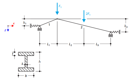
Una estructura hecha de cerchas de perfil en I está apoyada en ambos extremos mediante apoyos deslizantes de muelles y cargada por fuerzas transversales. The self-weight is neglected in this example. Determine the deflection of the structure, the bending moment, the normal force in the given test points, and the horizontal deflection of the spring supports.
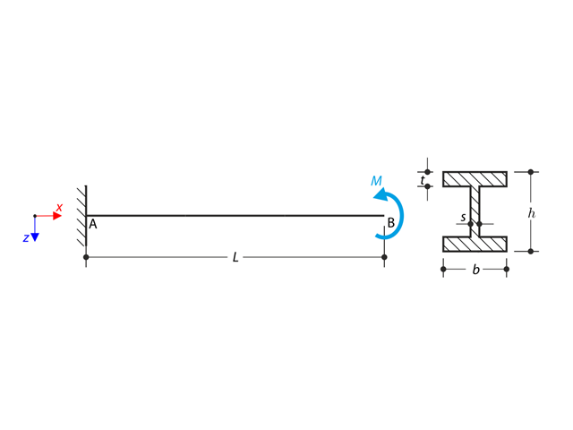
Un voladizo de perfil en I está apoyado en el extremo izquierdo y cargado por el par. The aim of this example is to compare the fixed support with the fork support and to investigate the behavior of some representative quantities. Comparison is also made to the solution by means of plates. Small deformations are considered, and the self-weight is neglected. Determine the rotation in the midpoint of the cantilever, and in case of the member entity with warping, determine the values of the primary torsional moment, the secondary torsional moment, and the warping moment both on the left end (point A) and the right end (point B).
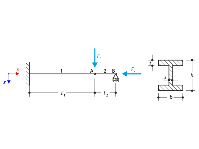
Una estructura hecha de un perfil en I está completamente fijada en el extremo izquierdo y empotrada en el apoyo deslizante en el extremo derecho. The structure consists of two segments. The self-weight is neglected in this example. Determine the maximum deflection of the structure, the bending moment on the fixed end, the rotation of segment 2, and the reaction force at point B by means of the geometrically linear analysis and the second-order analysis. The verification example is based on the example introduced by Gensichen and Lumpe.
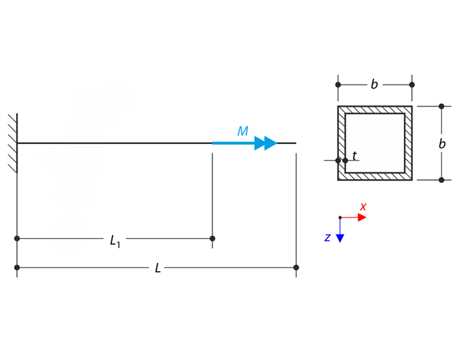
Un voladizo de pared delgada de un perfil QRO está completamente fijado en el extremo izquierdo y el alabeo está habilitado. The cantilever is subjected to torque. Small deformations are considered, and the self-weight is neglected. Determine the maximum rotation, primary moment, secondary moment, and warping moment. The verification example is based on the example introduced by Gensichen and Lumpe.
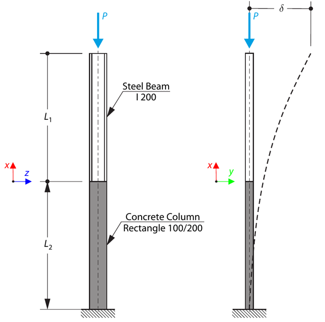
Un pilar se compone de una sección de hormigón (rectángulo 100/200) y una sección de acero (perfil I 200). It is subjected to pressure force. Determine the critical load and corresponding load factor. The theoretical solution is based on the buckling of a simple beam. In this case, two regions have to be taken into account due to different moments of inertia and material properties.
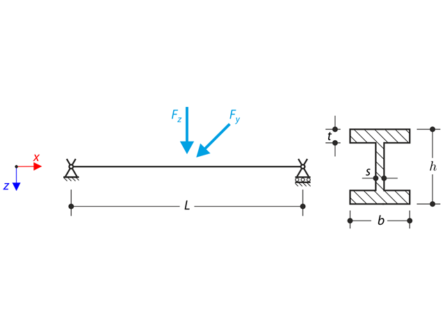
Una estructura hecha de un perfil en I está incrustada en los apoyos de la horquilla. The axial rotation is restricted on both ends while warping is enabled. The structure is loaded by two transverse forces in the middle. The verification example is based on the example introduced by Gensichen and Lumpe.
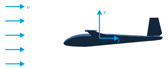
El objetivo de este ejemplo de verificación es analizar el flujo de fluidos alrededor de un planeador. La tarea consiste en determinar el coeficiente de arrastre y el coeficiente de sustentación con respecto al ángulo de incidencia. Estos coeficientes también se pueden dibujar en el gráfico de arrastre polar. El ángulo límite para el flujo de fluido laminar alrededor del perfil del ala también se puede determinar a partir del campo de velocidades. El modelo de CAD en 3D disponible (archivo STL) se utiliza en RWIND 2.
Una estructura hecha de perfil en I está completamente fijada en el extremo izquierdo e incrustada en el apoyo deslizante en el extremo derecho. La estructura consta de dos segmentos. El peso propio se omite en este ejemplo. Determine la flecha máxima de la estructura uz,max, el momento flector My en el extremo fijo, el giro &svarphi ;2,y del segmento 2 y la fuerza de reacción RBz por medio del análisis geométricamente lineal y el análisis de segundo orden. El ejemplo de verificación se basa en el ejemplo presentado por Gensichen y Lumpe.
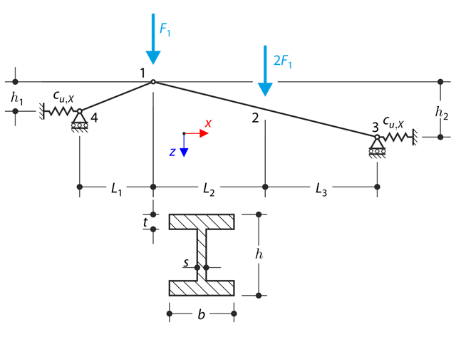
Una estructura formada por cerchas de perfil en I se apoya en ambos extremos por los apoyos deslizantes elásticos y se carga por los esfuerzos transversales. En este ejemplo se descuida el peso propio. Determine la flecha de la estructura, el momento flector, la fuerza normal en puntos de prueba dados y la flecha horizontal del apoyo del muelle.
Un voladizo de perfil en I está apoyado en el extremo izquierdo y está cargado con el par M. El objetivo de este ejemplo es comparar el apoyo fijo con el apoyo en horquilla e investigar el comportamiento de algunas cantidades representativas. También se realiza la comparación con la solución por medio de placas. El ejemplo de verificación se basa en el ejemplo presentado por Gensichen y Lumpe.
Un voladizo de pared delgada de un perfil QRO está completamente fijo en el extremo izquierdo y el alabeo es libre. El voladizo está sometido a un par. Se consideran las deformaciones pequeñas y se omite el peso propio. Determine el giro máximo, el momento principal, el momento secundario y el momento de alabeo. El ejemplo de verificación se basa en el ejemplo presentado por Gensichen y Lumpe.
El giro axial del perfil en I está restringido en ambos extremos por medio de los apoyos en horquilla (el alabeo no está restringido). La estructura está cargada por dos fuerzas transversales en su centro. El peso propio se omite en este ejemplo. Determinar las flechas máximas de la estructura uy,max y uz,max, el giro máximo φx,max, los momentos flectores máximos My,max y Mz,max y los momentos torsores máximos MT,max, MTpri,max, MTsec,max y Mω,max. El ejemplo de verificación se basa en el ejemplo presentado por Gensichen y Lumpe.